making the lathe more rigid
Stops & locks
A carriage lock is built in to the SC4 lathe. It is engaged by tightening an M5/0.8 socket-head cap screw (Sieg part #220) on the carriage. Tightening this screw pulls the Carriage Lock Block (Sieg part #231) up against the underside of the bed. Depending on the setup and position of the compound slide, access to the screw may be difficult.
The space in which a comfortable handle might be added to the screw is limited. Also, although not much rotation is needed to bring the screw from (loose enough) to (tight enough), a handle not capable of 360° rotation would need to include a screw of exactly the right length, with adjustments presumably necessary from time to time to account for wear.
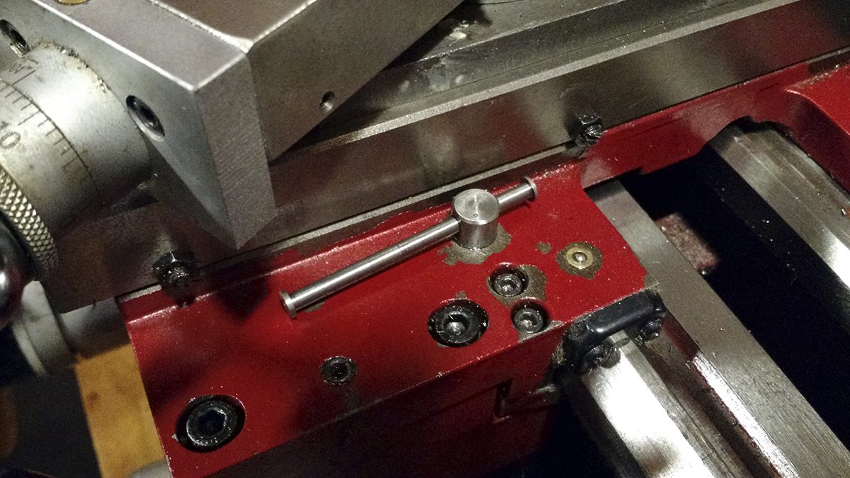
Drawing on some ideas that I found in this forum, I replaced the carriage-lock screw with a new screw that carries a sliding T handle. The Sketchup designs are here. and the finished part in situ looks like this:
Trying to move the carriage against the resistance of the carriage lock is not a good idea, and one might conclude that if loose is good, looser must be better. This is a mistake. If the Carriage Lock Block falls off the screw, it may vanish into the depths, requiring radical disassembly and reassembly of the saddle. To reattach the block to the screw, one must first remove the two M4/0.7 SHCSs (not numbered) just to the right of the carriage-lock screw; this will free the two-hole Rear Clamp (not numbered) whose right-hand face is seen at the right side of the saddle. Use a magnet to remove the Rear Clamp, and use the same (long) magnet to guide the Carriage Lock Block into position for its screw.
If the carriage-lock screw is tight but the carriage is still easily mobile, the carriage-lock block may have turned itself sideways. This can't happen if the screw is never made too loose.
Designs for carriage stops are easily found on the Web. One carriage stop should be made to carry a dial indicator. With a simple stop toward the headstock and an indicator-bearing one toward the tailstock, boring to a fixed depth is just a matter of
-
picking up the surface with the boring bar;
-
locking the right-hand stop close enough to the carriage so that the indicator engages the carriage;
-
zeroing the indicator;
-
moving the cross slide so that the boring bar clears the work;
-
advancing the carriage toward the headstock until the indicator shows the desired depth;
-
bringing the left-hand stop next to the carriage and locking it; and
-
repositioning the cross slide and boring, advancing the carriage toward the headstock until it runs into the stop.
Stops for the cross slide and compound are not quite as useful, but the effective rigidity of the lathe turns out to be strikingly improved when simple locks for the cross slide and compound can be engaged when these components should not move. The gib screws for the cross slide and compound can be tightened to achieve locking, but the screws provided with the lathe (Sieg #218 and #245) are shoddy, and their straight-slot heads make adjustment clumsy. I replaced all the gib screws with hardened, socket-headed setscrews (M4/0.7 × 16 mm for the rear of the carriage, M5/0.8 × 30 mm for the cross slide, and M3/0.5 × 16 mm for the compound). With the new screws in place, gib adjustment for locking and unlocking is easy.
Before attacking the gib screws, I had improvised locks for the cross slide and compound, relying on the existing threaded holes for the follow rest and for the compound rotation mechanism, respectively. These improvisations are now superfluous.
The mechanism that advances the lathe's tailstock quill is graduated in thousandths of an inch, and I have no reason to doubt its accuracy, but its backlash makes the scale almost valueless when a pecking technique is used for drilling. To drill to controlled depth, I use a collar that fastens to the quill and projects downward to where it can run into the carriage; a drawing for the collar is here. With the collar in place, drilling to fixed depth involves
-
picking up the surface with the drill bit;
-
locking the tailstock;
-
moving the carriage to run up against the bottom of the collar;
-
locking the right-hand stop close enough to the carriage so that the indicator engages the carriage;
-
zeroing the indicator;
-
advancing the carriage toward the headstock until the indicator shows the desired depth;
-
locking the carriage; and
-
drilling, advancing the quill until the collar runs into the locked carriage.
Coping with the 0XA quick-change tool post
The quick-change tool post most widely suggested for use with the SC4 lathe is the 0XA size; for example, see here. This QCTP is not adequate. The tool-post mounting hole on the SC4 lathe is M12/1.75, so the puny M6/1.0 central screw of the 0XA post must be fattened with an adapter before the post can be attached. With only this feeble attachment, it's difficult to keep the 0XA tool post from rotating away from its set orientation on the compound slide. Before I decided to get rid of the 0XA QCTP (see below), I developed a variety of coping strategies:
1. Sometimes one can do away with the tool post and/or compound slide altogether.
boring without the tool post or compound slide
One occasionally has reason to bore a tapered hole, but a boring bar should usually be parallel to the spindle. I built a boring-bar holder that replaces the compound slide. It is a one-trick pony, allowing no rotation about any axis except that of the spindle, and no height adjustment (the tool-holding hole was drilled by mounting a drill chuck on the spindle, so its height is guaranteed). A drawing (shared with the drawing of the QCTP mounting block described below) is here; the photograph shows this fixture in place on the cross slide.

a rotary broach that avoids the tool post and compound slide
Construction of a rotary broach, based on Mike Cox's design, is another application in which the compound slide can only get in the way. I started with another 2-inch-square tower screwed to a base plate. With the base plate tightened down to the cross slide at 90° and a drill chuck in the spindle, I drilled the hole in which the cutters would spin, and then I reversed the tower to drill the grease-escape hole. I didn't need the height-adjustment screw shown on Cox's site, nor — because I machined the 2°-angled cutter faces on the mill, using a 2° angle block and a 5C collet in square/hex collet blocks — did I need the locking screw that is present in the original design.
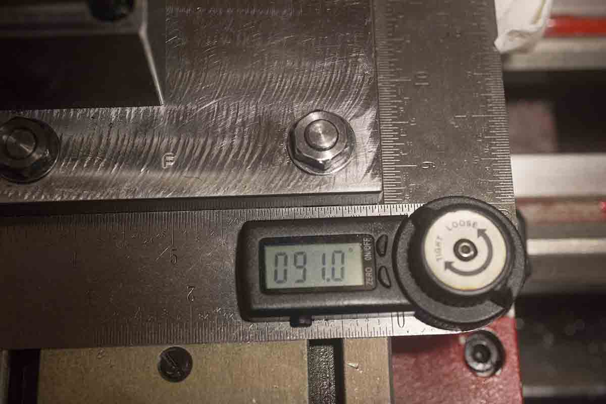
I didn't need to machine the sides of the tower to any specific angles at all. To skew the cutter to 1°, I simply twist the base plate as far counterclockwise as it will go before tightening down the nuts that hold it to the cross slide. As it turns out (the mounting holes are 0.358" ID; the T-bolts are M8/1.25), the limits of motion before the nuts are tightened are almost exactly ±1°.

mounting the 0XA QCTP without the compound slide
The compound slide can be rotated 360° on the cross slide, and the tool post can similarly rotate on the compound slide. Sometimes one wants the convenience of the QCTP, but the two potential rotations are troublesome. When parting, knurling, or using a form tool, the lathe must be configured to eliminate all these degrees of freedom, so that the tool is exactly perpendicular to the spindle.
I constructed a mounting block to support the 0XA QCTP in a fixed orientation. The block is attached directly to the cross slide in place of the compound slide. A drawing is here; the photographs show the block with and without the QCTP in place.


2. When the tool post and compound slide must both be used (for example, for threading), measures can be taken to increase the rigidity of the selected configuration.
tool-post positioning pin
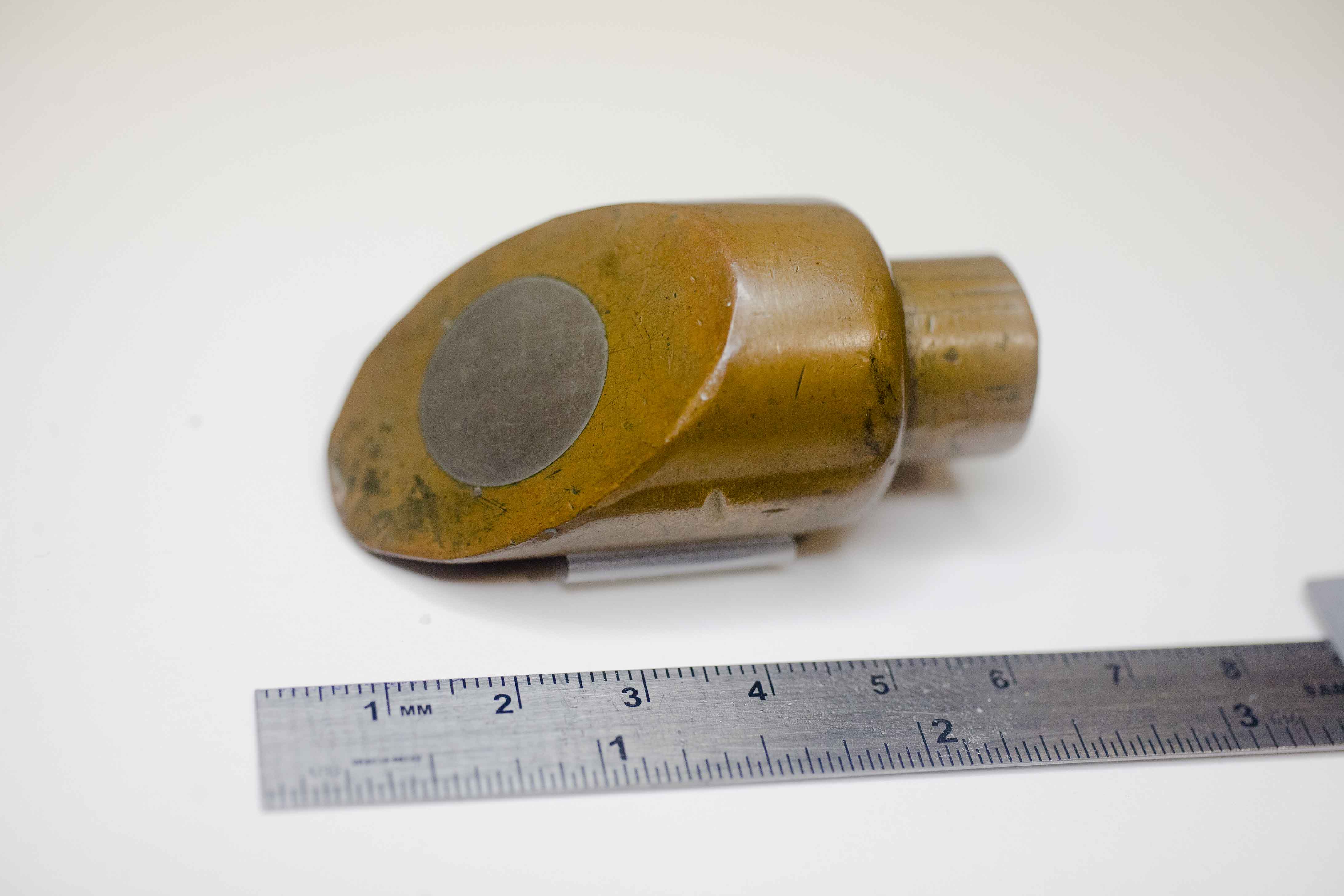
Unwanted rotation of the 0XA tool post is reduced by the Positioning Pin, Sieg part #238. This small part is spring-mounted in a well in the compound slide, from which it pushes a tooth up against the base of the tool post. I discovered that the Positioning Pin of my lathe had been lost, probably fired away by its spring during manipulation or replacement of the tool post. I believed (correctly) that it would be easy to fabricate another, but I was uneasy in the absence of any sort of drawing or description (the pin is shown on Sieg's assembly drawing of the lathe, but as little more than a smudge). I appealed to various Web-accessible sources of information, and I am happy to acknowledge the help of Luc Morin, who went to the trouble of dissecting his own C4 lathe and producing this elegant drawing. I made the replacement pin of mild steel. Along the way, I was struck by the uncanny similarity of shape between the Positioning Pin and this old xray anode that I happened to have around the house.
bracing the QCTP against unwanted rotation
To resist forces that might tend to rotate the tool post out of its orientation, I produced a simple brace that can be bolted to the compound slide. I made mine of 0.375" mild steel.


Installation of an AXA toolpost
My friend Alain Aubry showed me that an AXA QCTP can easily be fitted to the SC4 lathe, with immediate improvement in the rigidity of the system. There are two necessary adaptations before the AXA toolpost can be attached and used:
-
The AXA toolpost (at least the one I purchased) is provided with an attachment shaft that is said to be 9/16" OD, but in fact it is an M14/1.5 threaded rod. To attach the toolpost to the SC4 compound slide, I produced an M14/1.5 shaft that was turned down and threaded M12/1.75 for a centimeter or so at one end.
-
The AXA toolholders are beefier than their 0XA counterparts. When one of these toolholders is resting on the top of the compound slide, some tools will have their cutting edges above the lathe's center of rotation. Following Alain's lead, I milled relief, down to the level of the bottom of the T-slots, into the compound slide as shown here:
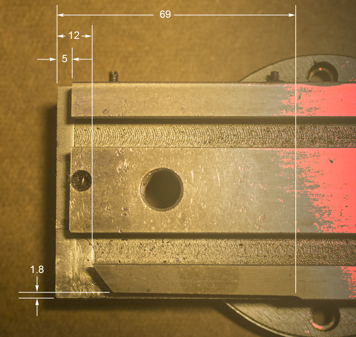
The AXA toolpost is more rigid than the old 0XA post, but it is liable to forced counterclockwise rotation when, for example, a cutoff tool must be extended to truncate a large-diameter workpiece. When using a cutoff tool, the compound slide is noncontributory, just as it is in the boring-bar case described above. Mounted on the cross slide in place of the compound slide, a simple frame (seen here bare and then with the QCTP mounted on it) provides solid protection against unwanted rotation.


Page revised: 01/28/2019 21:39