Sieg SC4 lathe: automatic stop & reverse
Especially when threading, I have often found myself hovering over the lathe's Reverse button or Stop button, anxiously watching the carriage as it moved toward the headstock, fated to crash if my attention lapsed. The person writing as "Synapsis" on this forum came up with the idea of a switch, triggered by by the advancing carriage, that would work in parallel with the Stop button to stop the lathe. I have adapted and expanded the ideas of Synapsis.
This PCB, found behind the lathe's front control panel,

hosts the switches that correspond to buttons on the panel. The Stop button makes the connection AB, the Forward button makes CE, and the Reverse button makes DF. All of these switches carry low currents, and when any of these switches is open, the voltage across it is less than 2 VDC. As shown by the annotations in the picture, each signal of interest appears in 2 or 3 places on the board.
Nearby behind the control panel is a little 13 VDC power supply. This supply
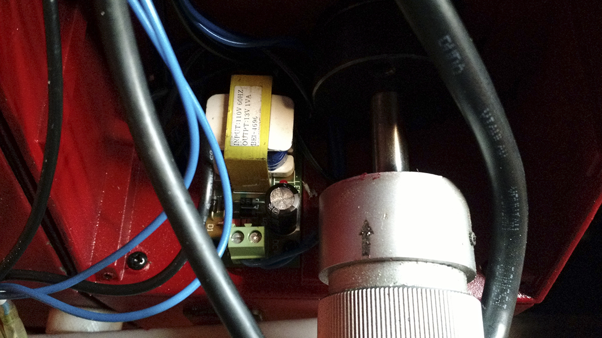
turns out to have ample spare capacity to drive modest additional circuitry.
After the lathe has been commanded to stop or reverse, it takes a while for the spindle (and therefore the carriage) to stop or reverse its motion. Depending on the spindle speed and the chuck in use, the stopping time can be anywhere from a few hundred milliseconds to almost 5 seconds, and, depending on the gears used to couple spindle rotation to carriage motion, during the stopping time the carriage will move anywhere from less than a millimeter to much of the length of the lathe bed. Watching signals from my timing light on the oscilloscope, one can estimate these stopping distances. For example, this picture

shows what was seen on the scope in one experiment. After closure of the switch, I counted pulses as shown in the annotations. Spindle rotation amounting to less than 1⁄32 revolution may have occurred before I started counting the 23⁄32 revolution and again after I counted the 28⁄32 revolution, so I conservatively estimate that after the Stop switch was closed, the spindle rotated (1 + 23)⁄32 + 8 + (28 + 1)⁄32 = 9.7 times. With the gears set for cutting a 20-pitch (1.27-mm) thread, the carriage would have traveled 1.27 × 9.7 = 12 mm after the Stop switch was closed. This result and others are shown in this table:
|
chuck: |
ER-32 collet | 100-mm 3-jaw | 125-mm 4-jaw | ||||||||||
|---|---|---|---|---|---|---|---|---|---|---|---|---|---|
|
chuck weight (kg): |
0.9 | 3.0 | 6.6 | ||||||||||
| indicated RPM: | 100 | 300 | 1000 | 2030 | 100 | 300 | 1000 | 2030 | 100 | 300 | 1000 | 2030 | |
| estimated maximum revolutions after Stop switch closed | 0.3 | 1.5 | 6.6 | 18.5 | 0.4 | 2.3 | 9.7 | 31.2 | 0.5 | 2.8 | 19.2 | 68.7 | |
| mm of carriage motion per revolution | TPI | ||||||||||||
| 0.05 | 0 | 0 | 0 | 1 | 0 | 0 | 0 | 1 | 0 | 0 | 1 | 3 | |
| 0.13 | 0 | 0 | 1 | 2 | 0 | 0 | 1 | 4 | 0 | 0 | 2 | 9 | |
| 0.25 | 0 | 0 | 2 | 5 | 0 | 1 | 2 | 8 | 0 | 1 | 5 | 17 | |
| 0.40 | 0 | 1 | 3 | 7 | 0 | 1 | 4 | 12 | 0 | 1 | 8 | 27 | |
| 0.50 | 0 | 1 | 3 | 9 | 0 | 1 | 5 | 16 | 0 | 1 | 10 | 34 | |
| 0.64 | 40 | 0 | 1 | 4 | 12 | 0 | 1 | 6 | 20 | 0 | 2 | 12 | 44 |
| 0.71 | 36 | 0 | 1 | 5 | 13 | 0 | 2 | 7 | 22 | 0 | 2 | 14 | 48 |
| 0.79 | 32 | 0 | 1 | 5 | 15 | 0 | 2 | 8 | 25 | 0 | 2 | 15 | 55 |
| 0.91 | 28 | 0 | 1 | 6 | 17 | 0 | 2 | 9 | 28 | 0 | 3 | 17 | 62 |
| 1.00 | 0 | 2 | 7 | 19 | 0 | 2 | 10 | 31 | 1 | 3 | 19 | 69 | |
| 1.06 | 24 | 0 | 2 | 7 | 20 | 0 | 2 | 10 | 33 | 1 | 3 | 20 | 73 |
| 1.27 | 20 | 0 | 2 | 8 | 24 | 1 | 3 | 12 | 40 | 1 | 4 | 24 | 87 |
| 1.41 | 18 | 0 | 2 | 9 | 26 | 1 | 3 | 14 | 44 | 1 | 4 | 27 | 97 |
| 1.50 | 0 | 2 | 10 | 28 | 1 | 3 | 14 | 47 | 1 | 4 | 29 | 103 | |
| 1.59 | 16 | 0 | 2 | 10 | 29 | 1 | 4 | 15 | 50 | 1 | 4 | 30 | 109 |
| 1.75 | 1 | 3 | 12 | 32 | 1 | 4 | 17 | 55 | 1 | 5 | 34 | 120 | |
| 2.12 | 12 | 1 | 3 | 14 | 39 | 1 | 5 | 20 | 66 | 1 | 6 | 41 | 145 |
| 2.31 | 11 | 1 | 4 | 15 | 43 | 1 | 5 | 22 | 72 | 1 | 6 | 44 | 159 |
| 2.54 | 10 | 1 | 4 | 17 | 47 | 1 | 6 | 25 | 79 | 1 | 7 | 49 | 175 |
| 3.18 | 8 | 1 | 5 | 21 | 59 | 1 | 7 | 31 | 99 | 2 | 9 | 61 | 218 |
(In practice, the angular momentum of a workpiece and the linear momentum of the carriage might increase these numbers, and drag of a tool in the workpiece might decrease them. I have made no pertinent measurements.)
After the carriage has moved so as to close a switch, the switch must somehow avoid being crushed before the carriage actually stops. As seen in the table above, allowance for post-switching travel of a few millimeters will be enough to avoid disaster with any of my chucks and any combination of gears, subject to certain restrictions on spindle speed.
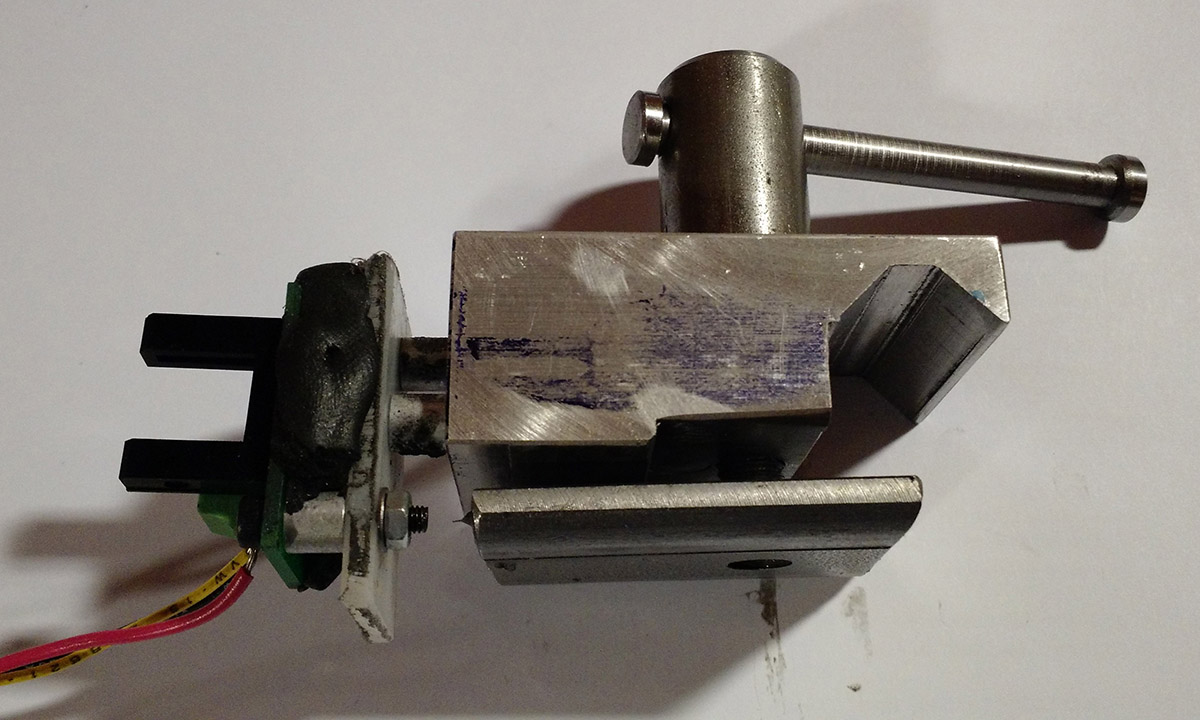
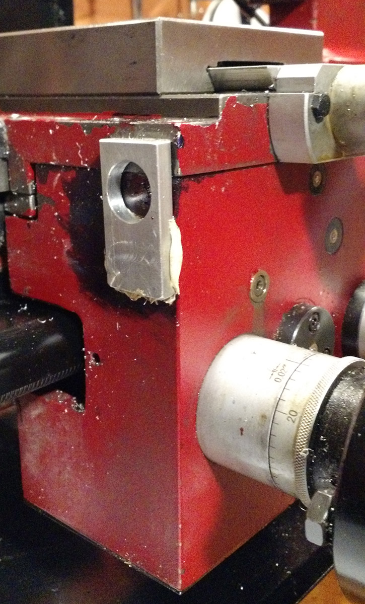
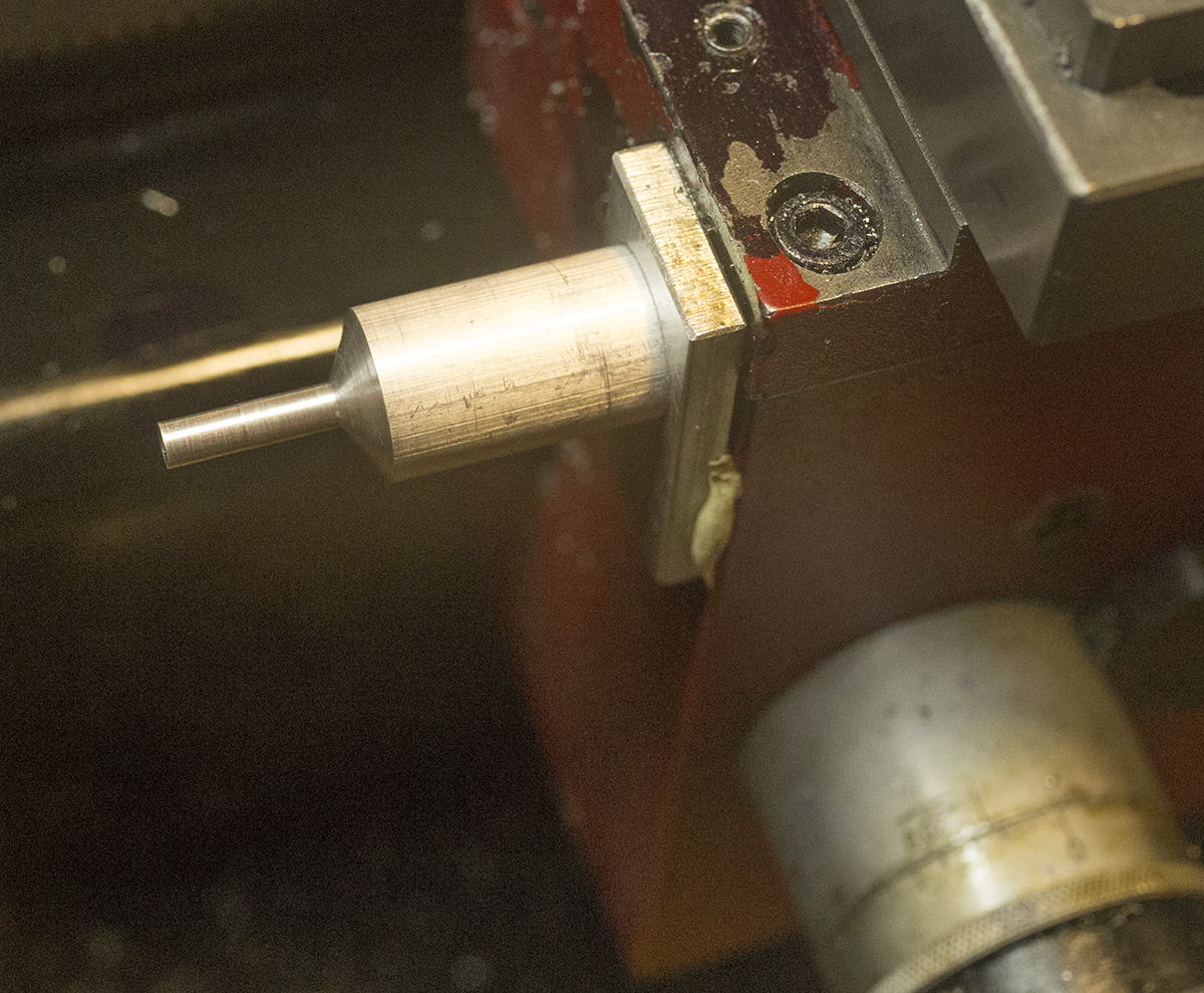
My system starts with a modified carriage stop, adapted to hold a photointerruptor. The beam of the photointerruptor is interrupted by a probe that extends from the left side of the carriage. The probe is long enough to allow for about 10 mm of travel after the beam has been interrupted. A SolidWorks image of the carriage stop and probe assembly is here, and the following pictures show the implemented carriage stop, the probe, and the probe support epoxied to the side of the carriage. The probe is shown together with a spacer whose use will be described.

A cable connects the photointerruptor on the carriage stop to a small printed-circuit board that is attached to the front of the control panel. The electronics there is connected to the 13 VDC power supply and to the points called A, B, D, and F in the first image above. The schematics are here, the Gerbers are here; and the DipTrace source is here.
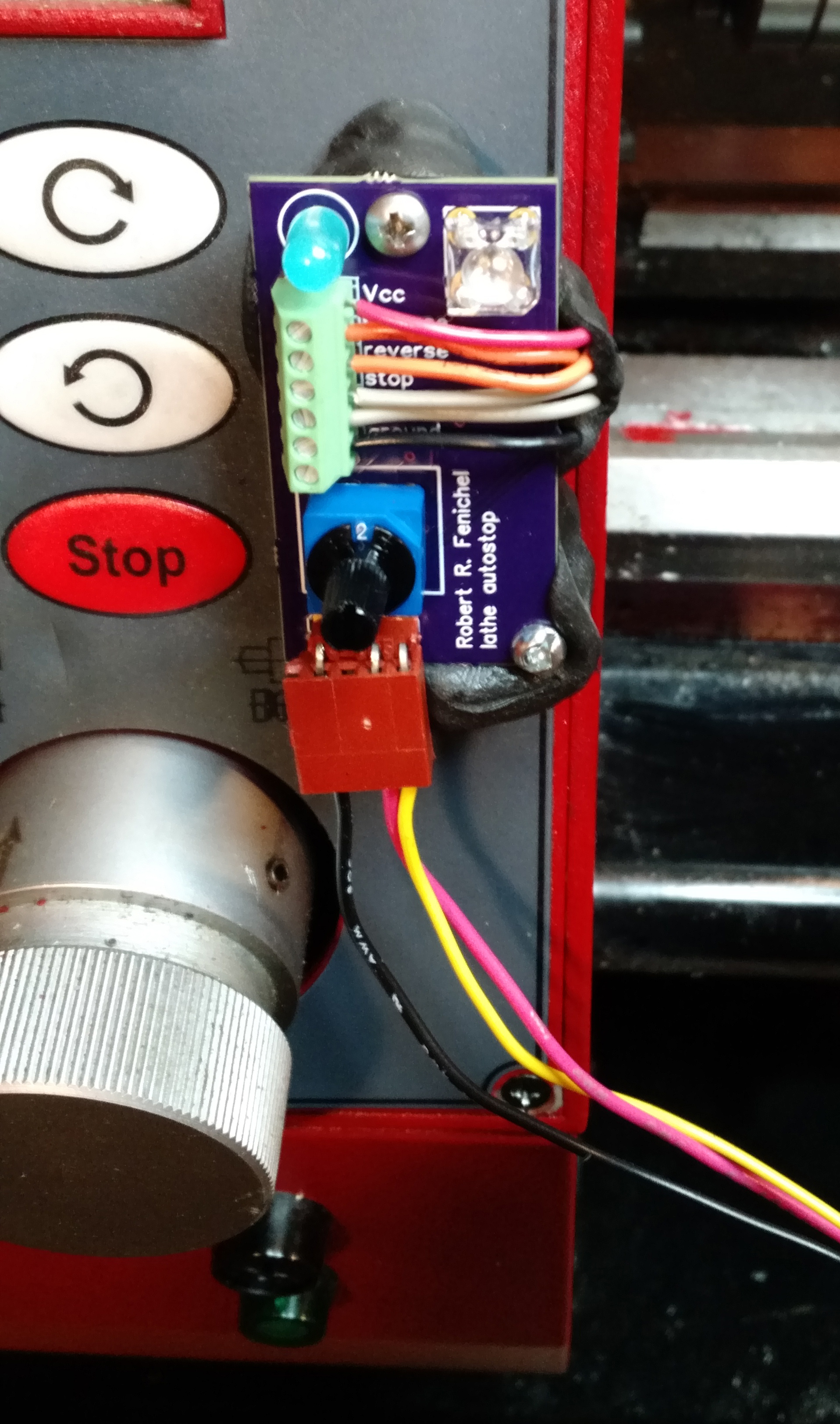
The central component of the circuit is a Toshiba TC4W66FU dual analog switch, similar to a pair of normally-open relays. The On resistance of each of the TC4W66FU switches is a few tens of ohms, but it turns out that the AB and DF switches are effectively closed by any bridging resistance less than 1500Ω or so. The rest of the circuit is a three-position switch (Stop on beam interruption, Off, Reverse on beam interruption), a bicolor LED to show the position of the switch, a blue LED to signal the interruption of the photointerruptor beam, and conventional support elements. Its power requirement is about 50 mA. Here are the connections to the Sieg PCB, and here also is my PCB installed on the lathe, with lots of black Sugru® in place to keep chips from poisoning the electronics:

To use this system, I attach the modified carriage stop loosely to the bed; I plug the photointerruptor on the carriage stop into the main PCB; and I turn the PCB's 3-position switch so that interruption of the beam will cause the lathe to stop or to reverse, whichever is desired. If the lathe power is on, then the red (stop) or green (reverse) LED lights up; if I probe the photointerruptor slot with a finger, then the blue LED lights up too.
Then, I place the spacer block on the bed between the carriage and the carriage stop
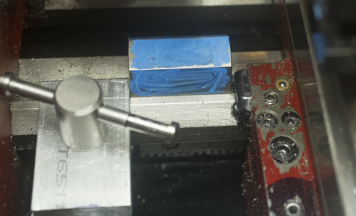
and I move the carriage leftward to the position at which, during operation of the lathe, I will want the lathe to stop or reverse. The carriage pushes the spacer block, and the spacer block pushes the carriage stop. When the carriage is at my chosen stop/reverse point, I clamp the carriage stop into position.
Finally, I withdraw the carriage to the right, I remove the spacer block from the bed, and I fit the probe into its socket on the carriage.
The lathe is then ready for use. When the carriage moves left, the appearance of the probe within the photointerruptor slot will cause the stop (AB) or reverse (DF) switch to be closed.
Page revised: 10/22/2016 17:13